Nowadays, the power of wireless transfer is studied by many companies, and researchers around the world are making charging systems for electric cars, mobile phones, and domestic electronics. One of the markets for this technology, which has a great social impact, is mobility vehicles for disabled and/or elderly people with limited autonomy.
While reviewing the prior art discussing mobility aids and the differences between frames, robots and the 3- and 4-wheel scooters, the most common use of scooters is the 4-wheel scooter base on the literature review (International, 2019) this type of scooters provide a better stabilizing function as well as a room for groceries and a comfortable sitting position, with 12- 20 V batteries and an output current 8-12A storing nominal energy reaching 240 Wh.
Since, these wireless power charging systems are already available in the marketplace, none are available especially for mobility scooters employing voltage ranges and current outputs. The goal of this research is to develop a power wireless transfer particularly designed for mobility scooters.
The wireless power transfer is defined by the transmitter (Tx) and receiver (Rx), which basically define the efficiency of the system as measured by the air gap length between the two coils. An Archimedean Spiral Design is proposed and simulated in MATLAB. Furthermore, a voltage control (PI) circuit is tuned, and experimental results are presented and elaborated. A prototype is developed with a maximum input voltage of 10 V and the air gap from 1 cm to 10 cm, with an efficiency of the system around 80% at 1 cm with a switching frequency of 100 kHz.
Mobility Vehicles
One of the most common symptoms in elderly people is the decreasing function of their musculoskeletal system with a higher tendency for women. Issues like osteoporosis and dorsal arthritis predominantly in those over age 60, almost always affect the hips and knees. Consequently, the loss of independence and a poor quality of life can affect their social life. Activities, which were once a part of their normal daily life, such as buying groceries or even having a medical appointment can become an excruciating and all-day marathon. Due to the reduction of mobility, depression, and isolation often develop in these types of patients. As a solution, medical aids have been developed. Some of these aids include wheelchair, frames, and mobility scooters. As an example, researchers have compared a walking frame, active which is the one with electrical motors and passive which has no motor on the prototype. The frame with motor is a regular walking aid, some of them can have on the top of the wheels, a 24 DC motor to control the torque and the speed. The system has a contact sensor to check if the user is on the frame and a lithium-ion battery with a nominal voltage of 25 V and 15 A as a current output in addition to a control box with AVRATMega 32A microcontroller is used.
On the other hand, MOD (mobility demand) services like Uber and Lyft have been helping users who tend to take a fast and safe transport method. Therefore, the most common solutions are mobility scooters, because they are autonomous and reliable. It is expected that the next generation of mobility includes autonomous vehicles, especially in cities like Singapore. Some of these vehicles have mapping and localization in 3D, dynamic re-planning path capability for online obstacles avoidance, and a web-based booking system. Also, it is mentioned how autonomous vehicles have been developed by model predictive equilibrium point control (MPEC), a control system consisting of the quick and responsible decisions taken by the vehicle .
As a summary of this research, a planner takes the decisions and plans the path for the user. Moreover, this system is using a camera in the seat, a computer with the ubuntu operation system, a joystick, and an STM32F4 microcontroller.
The electric characteristics of mobility scooters are studied,(Kim, 2015 ) where a scooter uses a DC brush motor and the mechanical commutation causes low power density, low reliability, and poor heat dissipation. One type of motor is the permanent magnet brushless motors (PMBCMS) that have high efficiency, low noise, low moment of inertia, and free maintenance. Nevertheless, this magnet motor can be divided into two categories, a Brushless Linear Motor (BLDM) with a trapezoidal back Electric Force Motors (EFM) and a permanent magnet synchronous motor (PMSM) with a sinusoidal back EFM. The claim of this study is to show how the PMSM has more efficiency than the other motors under a sinusoidal commutation. Besides, the electrical design in scooters, a PWM control method for a steering wheel in an electric mobility scooter is explained (B. Kim, 2012). Mainly a 4-wheel scooter is developed using an android tablet as a human-machine interface (HMI) and the control of the fourindividual wheel unit achieves the best performance in speed, low effort transport in a street environment.
Another kind of smart mobility vehicle is a robot scooter. An example of a robot with a complete autonomous mobility system running in an urban area with other robots and bicycles in the streets of Japan was developed. The navigation system of the robot, path following, obstacles avoidance, and grid map matching were presented (J. Sallan, 2009). A mobility scooter was modified with a SH 7125 microcontroller, DC gear, and a fiber-optic gyro TA60007, showing as a result an autonomous scooter robot running a 1.1 km in a real environmental area. Unfortunately, the aid solutions for elderly people sometimes have a problem with technical support, battery maintenance and life expectancy.
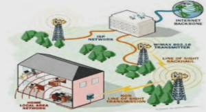
Therefore, companies such as Pride, Drive, and Metits have been studying the power wireless transfer technology as an environmentally suitable solution for better maintenance and life expectative of batteries. Usually, the batteries in those scooters must be changed after 6 months of daily use. The wireless power transfer (WPT) is a safe, convenient, and a smart solution for electric vehicles. However, these systems have less efficiency than their wired charging counterparts.
INTRODUCTION |


