L’interception et ses différentes lois de contrôl
METHOD
Participants
Eleven male and two female students (mean age 25 ± 2 years) gave their informed consent before participating in the experiment. They all had normal or corrected-to-normal vision, and their experience with ball games varied. A local ethics committee approved the experimental protocol.
Apparatus
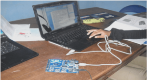
A general overview of the experimental set-up is presented in Figure 29. The set-up comprised a treadmill (Gymrol, BRL 1800), a large projection screen (2.3-m height × 3.0-m wide), a video projector (BARCO IQ 500), and two computers (cf., Bastin et al., 2006b; de Rugy, Montagne, Buekers, & Laurent, 2000). Participants walked on the treadmill, equipped with a 0.6-m wide × 1.80-m long moving belt that glided over a flat and rigid surface. Participants were attached to the back of the treadmill by means of a weight-lifting belt and a rigid rod, which allowed small vertical and sideward movements while participants walked on the treadmill. The projection screen was positioned in front of participants, at a distance of 0.70 m, providing a 118° × 130° field of view. The velocity of the treadmill was sampled via an optical encoder and sent by a RS-232 serial communication to a PC workstation that used this velocity to generate the movement of the visual scene. The visual scene was projected onto the screen by a video-projector at an update rate of 60 frames/s. The visual scene consisted of a textured ground plane (bricks), a 0.1-m wide brown displacement axis, and a spherical, moving, red target with a physical diameter of 0.22 m and an optical size that naturally expanded during the approaches. The spatiotemporal performance of the virtual environment is estimated to allow the visual consequences of a change in walking speed to be displayed within a maximum delay of 30 ms.
Experimental procedure
Before the experimental session, the initial velocity of the moving belt was individually adjusted until participants reported a subjective feeling of an easy walking pattern. The participant’s eye height with regard to the screen was also customized before the experiment. Once the participant stood on the treadmill, we measured his or her eye height and used this measure to compute the visual scene. At the start of each trial, participants were required to stabilize their walking speed between 1.15 and 1.25 m/s. To do so, a visual gauge was displayed on the projection screen, consisting of a vertical white line of 0.3 m representing the current velocity and a rectangular zone representing a velocity interval centered on 1.2 m/s. To satisfy the initial task requirements, the line had to be kept within the prescribed rectangular zone. When the prescribed velocity was maintained for 500 ms, the gauge disappeared and the trial began. The balls, which moved at eye height, had to be intercepted at the moment at which they crossed the displacement axis. To achieve this, participants regulated their walking speed, when deemed necessary, so as to be at the interception point at the right time (5 s after the balls appeared). Qualitative visual feedback was given: a green square was displayed at the end of successful trials and a red square at the end of unsuccessful trials. A trial was considered successful if the distance between the centers of the virtual ball and the participant’s head was less than 0.3 m at the moment at which the ball reached the interception point.
Independent variables
We manipulated the ball offset (three modalities), the curvature of the ball path (three modalities), and the display condition of the ball path (two modalities). The three offset conditions (i.e., different starting positions of the ball) were used in order to change the position at which the balls crossed the displacement axis (see Figure 30A). These positions were computed on the basis of the initial walking speed (1.2 m/s). In the absence of accelerations or decelerations, the balls would make contact with the head in the 0-m offset condition, pass 2-m in front of the head in the 2 m offset condition, and pass 2-m behind the head in the -2-m offset condition. The reason for manipulating the offset was to force participants to produce different displacement regulations and to prevent them from locating the place of arrival of the balls too easily. As also shown in Figure 30A, the balls approached along a rectilinear path (no curvature condition) or a curvilinear path (positive and negative curvature conditions; cf., Bastin et al.,2006b). In the curvilinear conditions, a constant curvature of ± 0.2 m-1 was achieved by making the ball move along (a portion of) an imaginary circle with a radius of 5 m, passing through the departure and arrival points of the ball. In half of the trials, the ball-pathdisplayed condition, the ball path was depicted in the virtual environment (see Figure 30B). This was achieved by displaying a 0.2 m wide stripe 0.4 m below the ball path throughout the trial duration. Preliminary tests had indicated that such a stripe allows participants to better discriminate ball path characteristics (i.e., curvature and place of arrival). Positioning the stripe on the floor was found to be less effective. In the remaining trials, the ball-path-notdisplayed condition, the ball approached without its path being depicted in the virtual environment.


