General description of the developed test rig
The general and essential requirements for a self-loosening machine are providing cyclic lateral displacement and the ability to measure preload and the studied parameters. Development of a test rig to study the effect of stiffness and grip length is the ultimate objective of the test rig. The stiffness of a bolted joint is a function of the material and the geometry of the bolt, mating parts, washers, and nut. Any changes in the material of the mating parts only change the stiffness whereas changes to thickness change stiffness and clamping parts simultaneously. Hence, the machine should be designed to also be able to measure other parameters so that they can be compared to the parameters that are influenced by grip length. To do so, the target machine should be able to measure at least rotation, lateral force, lateral displacement, and the number of cycles.
The design is based on an existing fatigue machine as the source of power to minimize the time and cost of the project. The original machine includes the following parts :
– Holding structure,
– Electrical motor,
– Adjustable crank system,
– Basic control panel for start-stop and frequency adjustment,
– Cycle mechanical counter with precision of 10 cycles,
– Lever with three loading point and spring end fulcrum,
– Mobile mounting structure,
– Grips and universal joint,
– Adjustable stem.
The holding structure, electrical motor, lever, mobile mounting structure, and adjustable stem are unmodifiable. The adjustable crank system is repaired and the cycle counter is bypassed and replaced by a magnetic digital counter. A basic control panel is connected to the designed control system and its outputs are transferred to the control and monitoring program. Speed control is directly connected to the electrical motor and the frequency can be adjusted manually.
The lever of the test rig is essentially a “class 2 lever”. The displacement provided by the electrical motor and crank system is applied to one end of the lever to produce the load and the test specimens can be installed between the universal joint and the load cell. According to work and energy law, with a certain amount of effort, the maximum load can be reached with the lowest displacement; hence, the closest point to the fulcrum point of the machine is used to install the test specimens in order to have the highest load capacity. The developed test rig is able to apply a lateral displacement from zero to 0.25 (inches) with a maximum frequency of 5000 cycles per minute. The maximum lateral force is 2000 lbs, which is a function of lateral displacement and stiffness of the joint in the lateral direction.
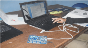
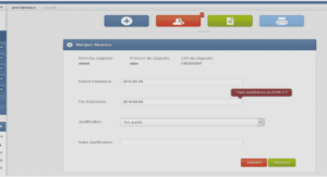
The control program is written in Lab View (Laboratory Virtual Instrument Engineering Workbench). This control and monitoring program can continuously display and record lateral displacement, lateral force, axial force, rotation, number of cycles, time and temperature. For safety reasons, the machine can be switched off via software or the control panel on the machine, but it can only be switched on from the control panel.
Requirements and limitations
Like in all experimental researches, measuring essential variables is the basic requirement of a test rig. Axial force, displacement, and rotation are the essential variables for the selfloosening test. Besides precision and measurement range being crucial factors for sensor selection, compatibility with the control system and measurement devices can be a limiting factor. Finding a feasible combination of available sensors is a challenge in the design of the measurement and control step.
The ability to test different plate thicknesses and bolt sizes is one of the desired specifications of the final test machine, which is limited by machine capacity. Increasing bolt size requires a higher transverse load to reach the same lateral to axial force ratio at the same bolt tightening stress ratio. Matching measurement accessories with different diameters and thicknesses limits the machine design with regards to feasibility, cost, and fabrication equipment. Limitations and their applied solutions are discussed in detail in each section.
In order to have realistic results, the joint geometry has to be kept, as much as possible, in conditions close to industrial applications. This requirement renders many measurement methods and devices ineffectual. using a load cell to measure axial load affects grip length and joint stiffness directly and creates significant changes in the results when studying joint stiffness. In the current study, the bolted joint is subjected to transverse load conditions, hence, the test rig has to be designed to avoid undesirable loads, such as bending while keeping pure transverse excitation.
When the stiffness of the joint is the subject of a study, it is very important to minimize the modifications made to the parts. Any excessive weakening or reinforcement will affect the properties of the joint and the test results. To meet this requirement, the coaxiality of the plates (mating parts), the fixed point, and the excitation point are considered as determinant factors. These geometrical restraints must be respected in all design modes (different plate thicknesses and their combinations).
INTRODUCTION |


